Consider an ASTM A992 W 18×50 beam forspan and uniform dead and live loads as shown in Figure 1. La barra está limitada a un canto nominal máximo de 18 pulgadas. The live load deflection is limited to L/360. The beam is simply supported and continuously braced. Verify the available flexural strength of the selected beam, based on LRFD and ASD.
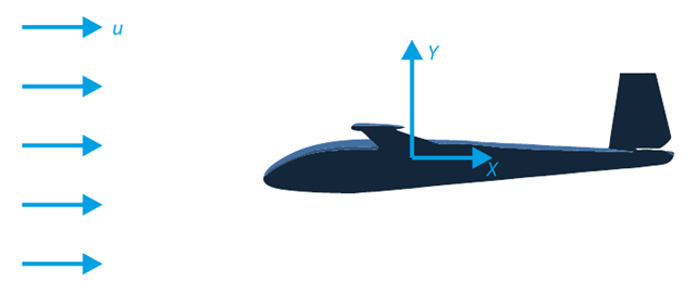
El objetivo de este ejemplo de verificación es analizar el flujo de fluidos alrededor de un planeador. La tarea consiste en determinar el coeficiente de arrastre y el coeficiente de sustentación con respecto al ángulo de incidencia. Estos coeficientes también se pueden dibujar en el gráfico de arrastre polar. El ángulo límite para el flujo de fluido laminar alrededor del perfil del ala también se puede determinar a partir del campo de velocidades. El modelo de CAD en 3D disponible (archivo STL) se utiliza en RWIND 2.
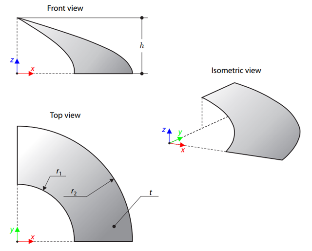
Una membrana se estira por medio de un pretensado isótropo entre dos radios de dos cilindros concéntricos que no se encuentran en un plano paralelo al eje vertical. Find the final minimum shape of the membrane - the helicoid - and determine the surface area of the resulting membrane. The add-on module RF-FORM-FINDING is used for this purpose. Elastic deformations are neglected both in RF-FORM-FINDING and in the analytical solution; self-weight is also neglected in this example.
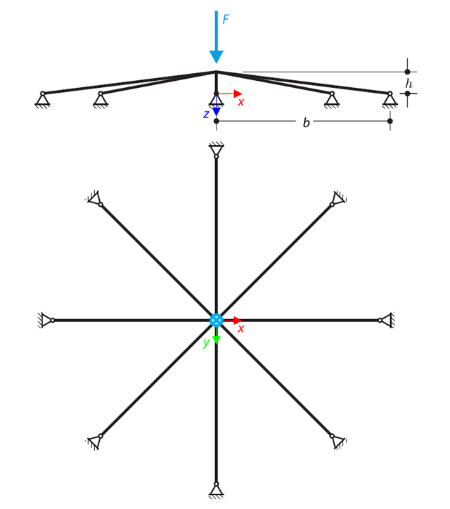
Una estructura superficial simétrica se compone de ocho barras de celosía iguales, que están incrustadas en los apoyos de las articulaciones. The structure is loaded by a concentrated force and alternatively by imposed nodal deformation over the critical limit point when the snap-through occurs. Imposed nodal deformation is used in RFEM 5 and RSTAB 8 to obtain the full equilibrium path of the snap-through. The self-weight is neglected in this example. Determine the relationship between the actual loading force and the deflection, considering large deformation analysis. Evaluate the load factor at the given deflections.
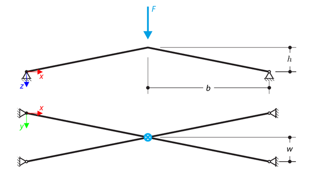
Una estructura se compone de cuatro barras de celosía, que están incrustadas en apoyos de articulación. The structure is loaded by a concentrated force and alternatively by imposed nodal deformation over the critical limit point, when snap-through occurs. Imposed nodal deformation is used in RFEM 5 and RSTAB 8 to obtain the full equilibrium path of the snap-through. The self-weight is neglected in this example. Determine the relationship between the actual loading force and the deflection, considering large deformation analysis. Evaluate the load factor at given deflections.
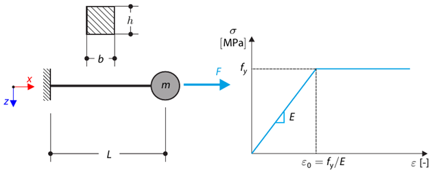
Este ejemplo de verificación se basa en el ejemplo de verificación 0122. A single-mass system without damping is subjected to an axial loading force. An ideal elastic-plastic material with characteristics is assumed. Determine the time course of the end-point deflection, velocity, and acceleration.
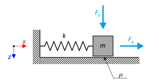
Un oscilador simple consta de una masa m (considerada solo en la dirección x) y un muelle lineal de rigidez k. The mass is embedded on a surface with Coulomb friction and is loaded by constant-in-time axial and transverse forces.
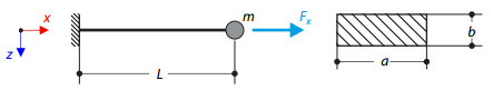
Un voladizo de sección rectangular tiene una masa al final. Furthermore, it is loaded by an axial force. Calculate the natural frequency of the structure. Neglect the self‑weight of the cantilever and consider the influence of the axial force for the stiffness modification.
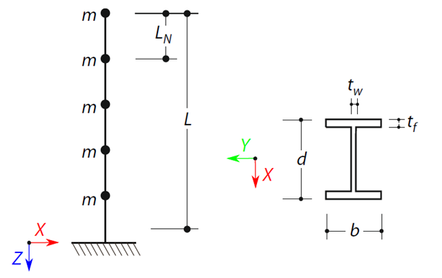
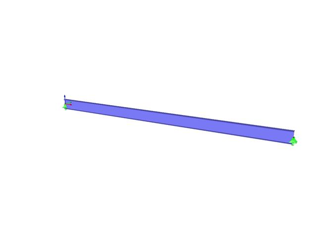
A cantilever beam with an I-beam cross-section of length L is defined. The beam has five mass points with masses m acting in the X-direction. Se omite el peso propio. The frequencies, mode shapes, and equivalent loads of this 5-DOF system are analytically calculated and compared with the results from RSTAB and RFEM.
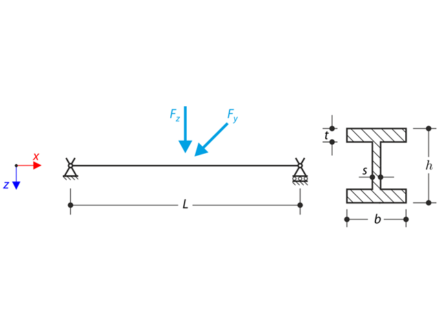
Una estructura hecha de un perfil en I está incrustada en los apoyos de la horquilla. The axial rotation is restricted on both ends while warping is enabled. The structure is loaded by two transverse forces in the middle. The verification example is based on the example introduced by Gensichen and Lumpe.